Rectifiers
Rectifier converts AC into DC.
We need DC voltages to run many of our appliances at home such as television, radio, computer etc.
Only lamps, fans etc can work on AC power directly. Therefore; we need to convert the AC main’s power received at our homes into DC in each of these gadgets to run them. Furthermore; it is only AC which can be stepped up and stepped down so easily. We can use a semi conductor on pn junction diode and convert AC into DC.
Types of Rectifier
Half Wave Rectifier
The half wave rectifier is made up of a diode and a resistor as shown in the fig. The half wave rectifier is used to eliminate either positive or negative part of the input.

Figure: Positive half wave rectifier
Negative Half Wave Rectifiers
Fig. shows a half wave rectifier with diode direction is reversed. In this circuit the diode will conduct on the negative half cycle of the input, and
VL = V2.
The diode will be reversed biases for the positive half cycle of the input and
VD = V2.
As a result positive half cycle of the input is eliminating. The operating principle of the negative half wave rectifier is same as the positive half wave rectifiers. The only difference is the polarity of the output will be reversed.

Figure: Negative Half wave rectifier
Full Wave Rectifiers
The full wave rectifier consists of two diodes and a resistor, as shown in the fig (a).

Figure: Positive full wave rectifiers
The result of this change in circuit is illustrated in fig (b).
In the fig (b), the output from the full wave rectifier is compared with that of a half wave rectifier.
Negative Full wave Rectifiers
The main differences between the positive and negative full wave rectifier are the direction that the diodes are pointing and the polarity of the output voltage.
The analysis of the negative full wave rectifier circuit is same as negative half wave rectifier.
If we reverse the direction of the diodes in the positive full wave rectifier, we will have a negative full wave rectifier as shown in the fig.

Figure: Negative full wave rectifier
Full Wave Bridge rectifier
The bridge rectifier is the most commonly used full wave rectifier circuit for several reasons
(1) It does not require the use of center-tapped transformer, and therefore can be coupled directly to the ac power line, if desired.
(2)Using a transformer with the same secondary voltage produces a peak output voltage that is nearly double the voltage of the full wave center-tapped rectifier. This results in the higher dc voltage from the supply.
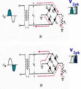
Figure: Bridge full wave rectifier
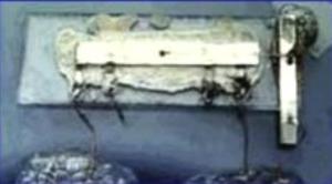
My Laboratory Experiment
I have created all the three rectifiers on a single board. It was a real fun for me. May be when I show the circuits; you people will not recognize that which circuit belong to a type of rectifier. I connected a 6V transformer to each of the rectifier and then observe their output on oscilloscope. The output produced was according to its operation.
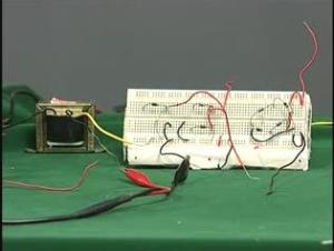
Figure: All the three rectifiers on single board